
Memory faults potentially endanger any kind of software running on an embedded system. The effects of RAM defects range from being negligible to wrong results or crashes. It is thus not a big surprise that, for safety-relevant software, the IEC 61508 requires the implementation of RAM tests as part of a Built In Self Test (BIST).
Depending on the safety integrity level, such RAM tests should be executed once at device start-up or in a cyclic manner during operation. The latter kind of RAM tests have to be non-destructive. This, however, excludes a number of very efficient testing techniques presented in this post.
RAM testing: A naive approach
The idea of any RAM test is to write a certain value to each RAM cell, to read from the same cell and make sure that the values written and read are identical. A simple test for 16 a bit memory could thus look like
x = first RAM address subject to testing;
  while x ≤ last RAM address subject to testing:
     write 0x0000 to address x
     read the value b from address x;
     verify that b = 0x0000;
     write 0xFFFF to address x;
     read the value b from address x;
     verify that b = 0xFFFF;
     x = x + 1;
This test can reliably make sure that there is RAM at all, and that the memory content survives a few clock cycles. But that’s all. The test is blind to cases where one address writes to two different memory cells, it is blind to cases where the address decoder ignores the most significant bit and thus cannot reach 50% of the memory. If the RAM is DRAM, the test cannot find out, if the refresh-logic does not work.
RAM becomes defective by radiation, high temperature, corrosion, or electrostatic discharge. If we want to reliably find a defect in any of its components, we need to look at physically possible defects in these chip components and thus deal with deterministic functional RAM chip testing.
RAM testing: A physical approach
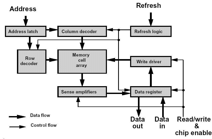
Figure 1 shows a functional model for a DRAM chip. The model suggests a number of possible physical defects and their functional impact. Amongst these defects are:
- Interruption of short circuits at the Chip Select or Read/Write lines.
- The content of a memory call can’t be changed.
- Cross-talk between memory cells.
- Certain cells can be set to 0 but not to 1 or vice versa.
- Certain bit patterns of neighboring cells prevent writing to another cell.
- One memory cell has more than one address.
Some of these different defects have the same effect on the black box. Thus, we may use a reduced defect model described in the subsequent three paragraphs [1].
Short circuits
The stuck-at fault causes a memory cell to always have the content 0 or 1. To make sure that your RAM is free of such simple defects, it suffices to read 0 and 1 successfully from each cell. Even the naive approach shown above will find such a defect. Unless it is masked by another defect in the address decoder (that causes the defective address not to be read).
Transition fault
If a memory cell cannot change from 0 to 1 or from 1 to 0, we speak of a transition fault. A test that wants to detect such a fault, has to trigger both transitions for each memory cell by a memory write and make sure that the write was successful by a following read instruction.
Coupling fault
When a so-called aggressor cell influences the content of a victim cell, we speak of a coupling fault. There are two variants:
- In case of the (more frequent) state coupling fault the state of the aggressor cell forces a certain state of the victim cell.
- The idempotent coupling fault means that a state transition in the aggressor cell forces a certain value in the victim cell.
March tests
The IEC 61508-7:2001 explicitly mentions a RAM test “March”. However, in fact, there is not one such test – there are numerous such tests and some of them are younger than the latest edition of the IEC 61508. I will introduce a small number of the members of the family and start with good old MATS++, which is defined as follows.
- (M1) Traverse all memory addresses in upward or downward direction and write 0 to all of them.
- (M2) Traverse all memory addresses in upward direction. Read the content of each cell and verify it is 0. Write 1, read, and verify that 1 has been read.
- (M3) Traverse all memory addresses in downward direction. Read the content of each address. Verify it is 1. Write 0, read, and verify that 0 has been read.
Step M1 is the initialization. M2 detects transition faults when transiting from 0 to 1 and faults of the address decoder. M3 also checks the decoder and finds transition faults for the change from 0 to 1. The 2nd and 4th read instruction are needed to reliably find transition faults in the presence of address decoder faults [1].
Almost always for such test descriptions, a short notation is used. The letters r/w denote the read/write accesses and arrows denote the increasing or decreasing sequence of addresses. In this notation, MATS++ looks as follows:
{↕(w0);↑(r, w1, r);↓(r, w0, r)}Well, MATS++ is comparatively fast but cannot reliably find coupling faults. However, that is no problem for „March C-“ [2]:
{↕(w0);↑(r, w1);↑(r,w0);↓(r,w1);↓(r,w0);↕(r)}RAM testing: Combinations of faults
It gets quite nasty when faults show up in teams. For example, when cell i is linked via a coupling fault with two different cells j, k. Accessing j could invert the content of i and accessing k could invert the content of i another time. Such linked faults might slip through ”March C-“. However, they will be detected reliably by “March B“:
{↕(w0);↑(r, w1,r,w0,r,w1);↑(r,w0,w1);↓(r,w0,w1,w0);↓(r,w1,w0)}OMG you will say! The many successive write operations are essential for the detection of linked coupling faults. The many read operations in the second block prevent a transition fault from being masked by a coupling fault. “March B” detects all combinations of all faults of the defect model presented so far. The model, however, does not include the refresh logic of DRAM.
RAM data loss testing
A data retention fault (DRF) occurs when a memory cell loses its previously stored logic value after a certain period of time during which it has not been accessed. This is typically due to a defect in the refresh logic of a DRAM, but loss of data over longer periods also has been observed for SRAM. The following test looks for a DRF. RAM manufacturers run such tests at high temperatures because the likelihood of DRFs dramatically increases with high temperatures. The waiting times are typically between 100 and 500ms.
{↕(w0);wait;↑(r,w1);wait;↑(r)}Dynamic faults
We will go one step further and extend our fault model by a very mean kind of dynamic memory faults: dirty faults. A read access, that directly follows a write access, changes the data of a cell but the read access nevertheless gives the previous correct data. This awful fault can show up in reality and test “March RAW” (read after write) finds it for us.
{↕(w0);↑(r,w0,r,r,w1,r);↑(r,w1,r,r,w0,r);↓(r,w0,r,r,w1,r);↓(r,w1,r,r,w0,r);↕(r)}Readers, who are interested in what physically must happen in a chip for such a dirty fault to appear, are referred to [3].
You cannot find all
When you search the internet for RAM tests, you will find fault models that cover much more than what I have presented in this post. Most prominent among what we have not covered are Neighborhood Pattern Sensitive Faults (NPSF). An example of a fault of this family is the case where a cell changes its data because of the change of the bit pattern in its neighborhood on the chip. Tests that look for NPSF are typically run by chip manufacturers, not by users. The detection of NPSF is hard for end users of RAM because they do not know the chip architecture.
If the developers of a safety-critical electronic device implement March B or March RAW and another test that looks for DRF, to my opinion then they do a very good job. The tests won’t find all memory faults that are possible, but the most probable ones for sure. The direct consequence of the fact that a BIST cannot find all RAM faults is already reflected in the many recommendations of the IEC 61508. For systems of high integrity levels, these recommendations include the use of error detection codes, parity bits and hardware redundancy.
Acknowledgments
Many thanks to Prof. Ad van de Goor for help and advice. Ad van de Goor is a professor emeritus from the TU Delft.
References
- Ad J. van de Goor, C. A. Verruijt: An Overview of Deterministic Functional RAM Chip Testing. ACM Computing Surveys, Vol. 22, No. 1, March 1990.
- A. J. van de Goor, Testing Seminconductor Memories, Theory and Practice. ComTex, Publishing Gouda, NL, 1998.
- S. Hamdioui, Z. Al-Ars, Ad J. van de Goor, M. Rodgers: Dynamic Faults in Ramdom-Access Memories; Concept, Fault Models and Tests. Journal of Electronic Testing: Theory and Applications, Vol 19, 2003, pages 195-205.
1 thought on “Testing RAM in high-integrity embedded systems”
Very nice article. I came across this march algorithm in my current project and looking for a understanding of it. This is well written and clear.